
LOGICAL GATES
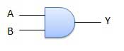
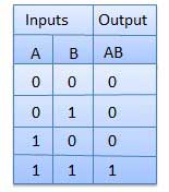
AND Gate:--
A circuit which performs an AND operation is shown in figure. It has n input (n >= 2) and one output.
Logic diagram
Truth Table
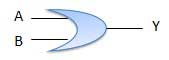
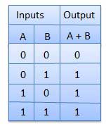
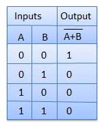
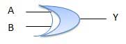
OR Gate:--
A circuit which performs an OR operation is shown in figure. It has n input (n >= 2) and one output.
Logic diagram
Truth Table
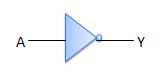
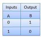
NOT Gate:--
NOT gate is also known as Inverter. It has one input A and one output Y.
Logic diagram
Truth Table
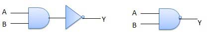
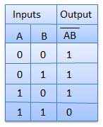
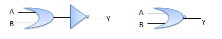
NAND Gate:--
A NOT-AND operation is known as NAND operation. It has n input (n >= 2) and one output.
\Logic diagram
Truth Table
NOR Gate:--
A NOT-OR operation is known as NOR operation. It has n input (n >= 2) and one output.
Logic diagram
Truth Table
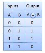
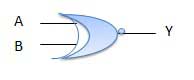
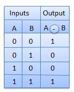
XOR Gate:--
XOR or Ex-OR gate is a special type of gate. It can be used in the half adder, full adder and subtractor. The exclusive-OR gate is abbreviated as EX-OR gate or sometime as X-OR gate. It has n input (n >= 2) and one output.
Logic diagram
Truth Table
XNOR Gate:--
XNOR gate is a special type of gate. It can be used in the half adder, full adder and subtractor. The exclusive-NOR gate is abbreviated as EX-NOR gate or sometime as X-NOR gate. It has n input (n >= 2) and one output.
Logic diagram
Truth Table


No comments:
Post a Comment